
Guide to the whole process of debugging the hydraulic station of CNC machine tools
Date: 2025-03-24 Categories: Hydraulic station information Views: 12556
article directories[Hidden]
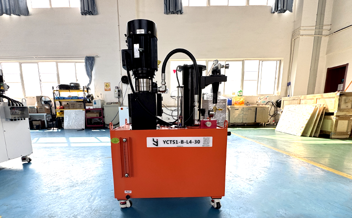
In the overall performance of CNC machine tools,hydraulic systemThe debugging quality directly affects the machining accuracy and equipment reliability. This article is based on hydraulic transmission standards and combines with the experience of servo hydraulic station debugging to explain in detail the entire process method from basic debugging to high-level optimization.
1、 Preparation stage before debugging
- Hardware Verification Checklist
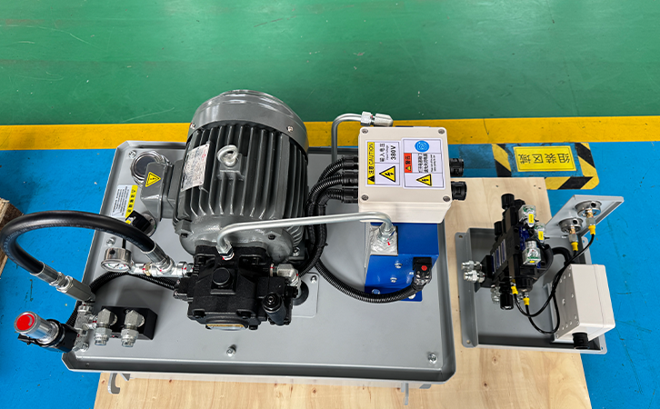
- Confirm the configuration of the hydraulic station:
▪ Main pump type (variable/quantitative) and rated parameters
▪ Compatibility of valve group functions (direction/pressure/flow valves)
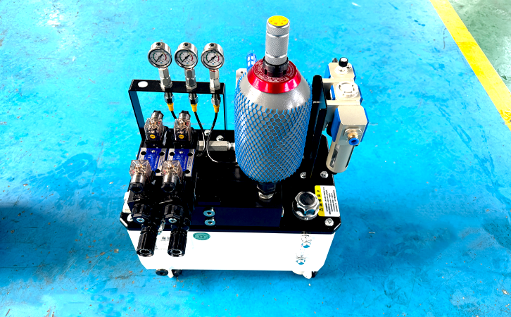
▪ Pre charging pressure of accumulator (should be 25-30% of system pressure) - Preparation of testing tools:
▪ 0.5 level pressure gauge (with a range covering 150% of the system pressure)
▪ Infrared thermal imager (temperature resolution ≤ 0.1 ℃)
▪ Flow meter (accuracy ± 1% FS)
- System Pre check Specification
- Oil cleanliness verification:
▪ New oil meets ISO standards
▪ After flushing the pipeline, it needs to reach level 16/14/11 - Sealing test:
▪ No load holding pressure for 30 minutes, pressure drop ≤ 0.5MPa
▪ 24-hour static leakage rate < 0.1% system volume
2、 Six step basic debugging method
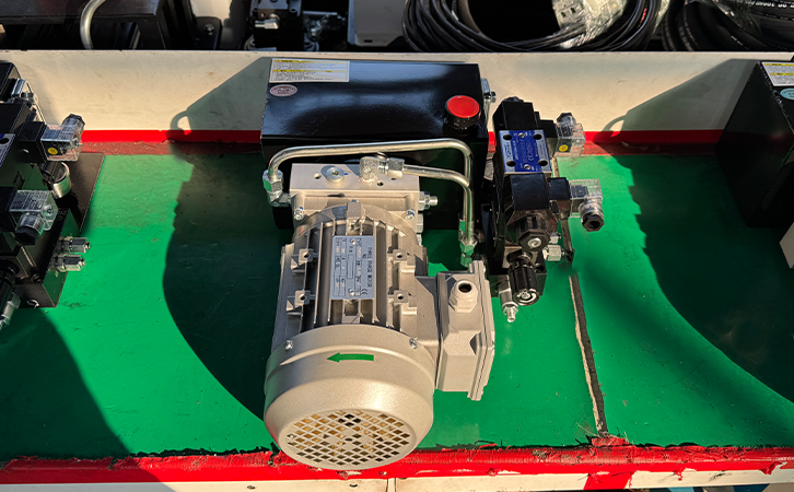
Step 1: Power unit no-load start
- Jogging the motor to confirm correct rotation direction (direction of oil splashing)
- Run without load for 30 minutes, check:
▪ Pump body vibration value ≤ 4.5mm/s (GB/T 29531 standard)
▪ Fuel tank temperature rise ≤ 2 ℃/10 minutes
Step 2: Initial adjustment of overflow valve
- Gradually increase the system pressure to 80% of the rated value
- When using PID control, the automatic adjustment function needs to be turned off
- Debugging tools:
▪ Special locking wrench for overflow valve (to prevent misoperation)
▪ Pressure step tester (recording response time)
Step 3: Calibration of actuator travel
- Hydraulic cylinder reciprocating 3 times to eliminate air
- Set soft limit buffer (10% travel buffer segment)
- Positioning accuracy detection:
▪ Servo cylinder repeat positioning error ≤± 0.02mm
▪ Ordinary cylinders require mechanical block compensation
Step 4: Dynamic matching of traffic
- Adjust the flow rate of each branch through a proportional valve:
▪ Fast forward operating condition: flow tolerance ± 5%
▪ Working conditions: flow tolerance ± 2% - When using a throttle valve, synchronous detection is required:
▪ Stable flow rate (≤ 5% of rated flow rate)
Step 5: Thermal balance debugging
- Test after 4 hours of continuous operation:
▪ The oil temperature remains stable at 40-55 ℃ (machine tool ≤ 50 ℃)
▪ Abnormal when the temperature difference between the inlet and outlet of the cooler is greater than 8 ℃ - Thermal compensation setting:
▪ Viscosity compensation coefficient setting (refer to ISO VG32 characteristic curve)
Step 6: Safety interlock verification
- Pressure relay action value test:
▪ Low voltage alarm point=set value x 85%
▪ Overpressure shutdown point=set value × 115% - Emergency stop response time ≤ 0.5 seconds
3、 High-order parameter optimization
1. Pressure pulsation
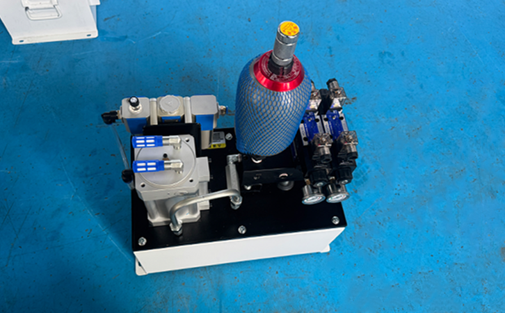
- Installation location optimization:
▪ The distance between the accumulator and the pump outlet is ≤ 1.5m
▪ When the length of the hose is greater than 300mm, a pipe clamp needs to be added - Pulsation control standard:
▪ Variable pump system ≤± 0.5MPa
▪ Quantitative pump system ≤± 1.2MPa
2. Dynamic response improvement
- Principle of PID parameter tuning for servo system:
▪ Proportional band: Adjust according to step response overshoot (recommended 5-15%)
▪ Integral time: Take 3-5 times the natural frequency of the system
▪ Differential time: take 1/4-1/3 of the integral time - Test signal:
▪ Frequency 0.1-10Hz sine wave sweep test
3. Energy efficiency optimization plan
- Adopting a load sensitive system (LUDV) can achieve an energy-saving rate of up to 40%
- Night mode setting:
▪ Standby pressure drops to 30% of working pressure
▪ Pump displacement automatically switches to maintenance level
4、 Typical Fault Handling Guide
| Fault phenomenon | diagnostic points | Solution |
|---|---|---|
| Pressure oscillation | Check the pre charging pressure of the accumulator | Supplement nitrogen to 90% of the set value |
| Execution mechanism crawling | Detecting oil with a gas content greater than 3% | Add a vacuum dehydration device |
| Abnormal temperature rise | Cooler fouling coefficient>0.001 m ² ·℃/W | Chemical cleaning or replacement of fins |
| Electromagnetic valve stuck | Detecting coil impedance deviation>15% | Use specialized demagnetization tools for processing |
5、 Debugging Case Analysis
Case 1: Five axis machining center tool change fault
- Phenomenon: Hydraulic motor reversal impact in the tool magazine causes positioning deviation
- Debugging process:
▪ Add 5ms ramp time to the proportional valve control signal
▪ Adjust the opening pressure of the buffer valve to 120% of the working pressure - Result: The impact force of tool change was reduced by 60%, and the positioning accuracy was restored to ± 0.01mm
Case 2: Large gantry milling beam settlement
- Phenomenon: The hydraulic lock of the crossbeam slowly slides down after stopping the machine
- Improvement measures:
▪ Stacked hydraulic control one-way valve (pilot ratio 1:4)
▪ Set up dual pressure monitoring interlock - Effect: 72 hour settlement reduced from 3mm to 0.05mm
Conclusion
The fine debugging of hydraulic stations needs to follow the principle of "static first, dynamic second, rough first, fine second"It is recommended to establish a debugging parameter file (including the set values and testing data of each valve component) and conduct regular preventive maintenance. With the development of electro-hydraulic fusion technology, future debugging will rely more on digital twin technology to achieve virtual debugging. At this stage, it is still necessary to pay attention to the standardized execution of traditional debugging processes.
Disclaimer: Each machine tool has different design standards, and this article is for reference only!